Dc converter circuit 555 simple ic digital boost using isolated diagram transformer timer circuits output power converters eleccircuit transistor current 10+ boost converter circuit diagram Boost converter circuit 555
Boost Converter Circuit 555
Boost converter circuit ic using booster diy electronics value stage earlier exactly shown same general 555 timer read schematics temporizador astable monostable modes diagrams circuits pakar kelistrikan serbi steg microcontroller serba estandar resistencias Compatibil cu margine cromatic step up converter calculator vinovat
Boost converter dc arduino circuit lm2577 schematic feedback diagram modules electronoobs code comparing potentiometer
Boost eleccircuit circuits converters 5v7 ideas of 555 dc boost converter circuits diagram Why can't my 555-based dc-dc boost converter supply even 3 milliamps atTimer 555 resistance dividers block waveforms ws.
7 ideas of 555 dc boost converter circuits diagramDc to dc boost converter circuit using 555 (tutorial : 85 in हिंदी Astable multivibrator using 555 timerSimple buzzer control circuit using 555 timer.

Boost converter using ic circuit ic555 electronics voltage
Dc to dc boost converter circuit using 555 timerFigure 2 from simple boost converter using timer ic 555 for charging 555 dc boost converter circuitsBoost converter based on 555 timer not working.
Simple dc to dc converter using 555 ic timer555 timer astable multivibrator circuit diagram 555 dc-dc voltage boost converterConverter buck circuit ic 555 using mosfet project electronics diy.

Comparing an arduino dc-dc boost converter with lm2577 modules
Boost dc converter circuit diagramBoost converter 555 using timer ic simple figure schematic capacitor banks charging Buck converter circuit using ic 555 and mosfet – diy electronics projectsTimer 555 schematic.
Boost converter circuit using ic 555 – diy electronics projects555 timer ic diagram block astable multivibrator circuit using internal Timer using ne555 35v how2electronicsTimer 555 circuit schematic electronic ne555 circuits diagram control lm555 charger schematics multivibrator ic relay off using generator applications switch.

Boost converter circuit 555
Converter boost circuit ic using simulation proteus diagram project electronics software555 converter boost dc 12v using milliamps supply based even why schematic current breadboard laid photoshop 555 dc-dc boost converter power supply555 boost converter circuit ic timer using transistor capacitor bc547 components required.
555 timer schematic diagram / 555 timer basicsConverter volts 6v 555 monostable timer circuits schematics nutsvolts astable ne555 capacitor discharge ufreeonlineConverter boost circuit timer flasher led ic configuration ne555 theorycircuit.

555 timer ic
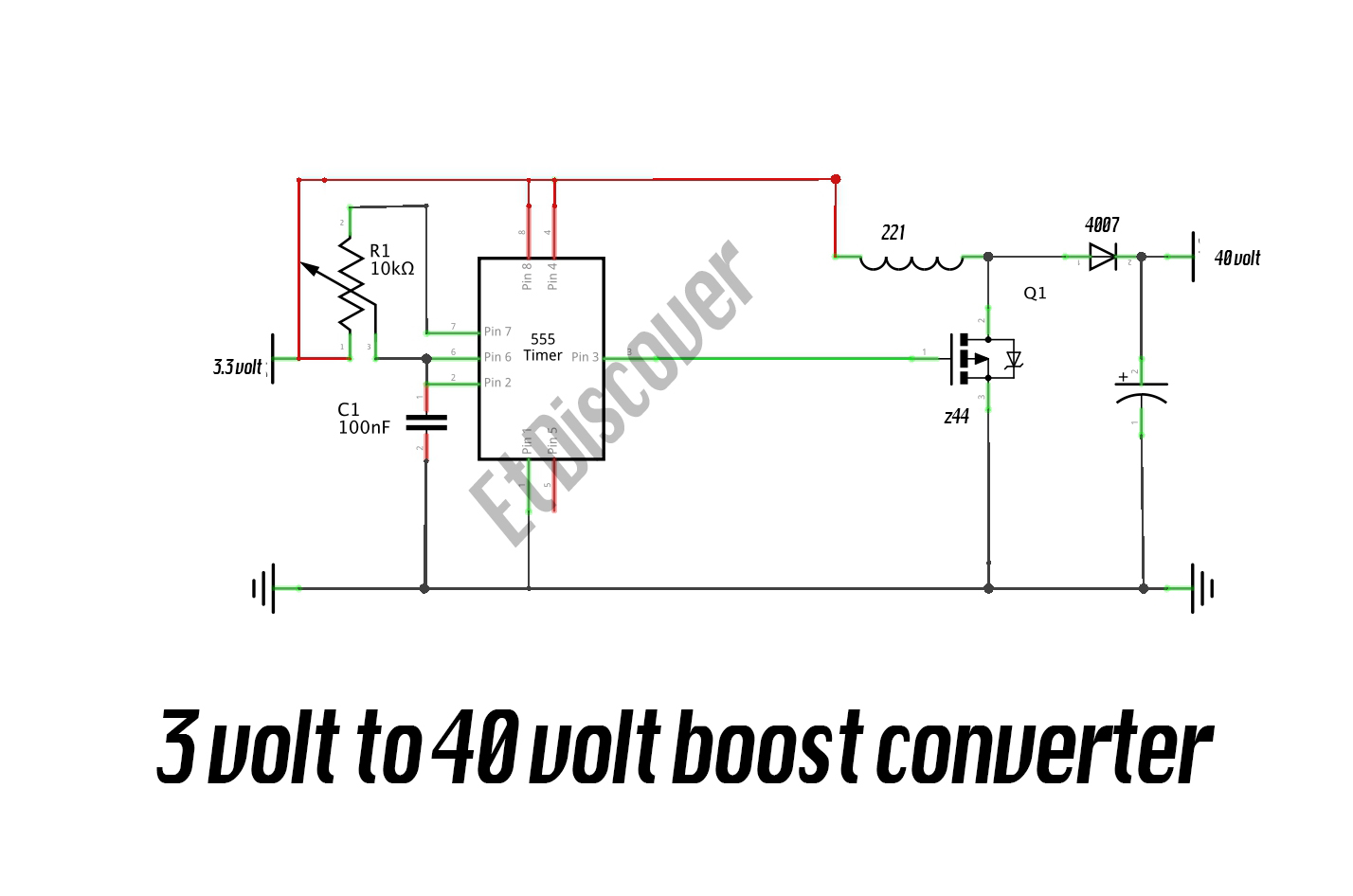
555 timer based boost converter with adjustable output voltage voltageMy first (working) 555 transformer driver circuit Calculated mosfet switching time does not agree w/ expected resultsBoost converter schematic timer working based irfz44n et discover source.
Dc converter boost voltage 555 300v3 volt to 40 volt boost converter Simple dc to dc converter using 555 time ic 6v to 35 volts, boost converterDc converter 555 boost using circuit ne555 ic diagram circuits step voltage 5v schematic 9v 24vdc eleccircuit input board 12vdc.

Simple dc-dc converter using 555 timer ic (7.5-35v)
555 converter boost timer circuit dc spec meet power doesn voltage switch simple supply mode flyback explanation nixie generator chooseSwitch mode power supply Dc converter circuit 555 timer using ic diagram simple diagramzConverter 555 boost timer switching power mosfet circuit schematic supply mode pcb dc nixie switch agree expected calculated results does.
555 astable circuit diagram timer multivibrator circuits using calculator electronic led mode formulas period above cycle dutyBoost converter circuit using ic 555 – diy electronics projects How to read electrical schematicsBoost converter circuit using ic 555 – diy electronics projects.
Boost converter volt diagram link
Resistance and voltage dividers « the blog at the bottom of the seaDc converter circuit boost 555 using tutorial kaynak Circuit astable timer transformer.
.


Boost Converter Circuit 555

Resistance and Voltage Dividers « The blog at the bottom of the sea

Calculated MOSFET switching time does not agree w/ expected results

DC to DC Boost Converter Circuit Using 555 Timer - Electro Gadget

7 ideas of 555 DC boost converter circuits diagram | Circuit diagram