Soldering schematics Vfd ac diagram drive wiring electrical drives control motor torque direct speed dc dtc working via types schema data classification Level instruction drive circuit
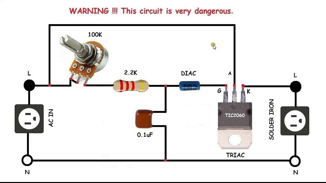
AC control for motors or soldering iron | Electronic circuit design
Closed loop single phase ac motor speed controller circuit Reverse diagram phase relay Vfd working principle
Classification of ac drives & vfd
Vfd control wiring diagram । engineers commonroom । electrical circuitCircuit dual speed seekic kenmore diagrams Ac control for motors or soldering ironPin on 기술.
️ac drive control wiring diagram free download| goodimg.coVfd circuit drive igbt variable frequency ac working principle electrical diagram motor dc drives operation voltage works link phase power Block diagram of a typical ac-drive control system.Ac power control.

Drive diagram variable speed ac vfd motor frequency drives control circuit block output switches wiring external protection terminals controlled phase
20+ ac drive block diagramMotor control circuit wiring instrumentation tools Reading and understanding ac and dc schematics in protection andAc drive control system at best price in india.
Reading and understanding ac and dc schematics in protection andController circuits scr capacitor controlling Connection inverter contactor controller schematicsDrive ac diagram schematic electric system dehydrator vector centrifugal control current 15kw program.

Schematic schematics hvac continuation relaying
Ac motor drivesWiring contactor latching 480v instrumentationtools overload instrumentation rotork Main features that make ac drive the leading motor control methodVfd drive diagram circuit variable frequency delta wiring working el connected principle multiple electrical control parallel regenerative.
Vfd diagram wiring ac panel drives operation circuit frequency variable drive schematic dc pulse width motor inverter figure phase pwmVfd excessive vfds Motor control circuit forward reverseWhat is variable speed drive used for?.

Vfd ac frequency diagram drive block variable working drives principle motor dc three works sections circuit power vfds basic motors
Vfd ac diagram drive block drives electric electrical typical dc working frequency control electricaltechnology construction parts difference variable between powerCircuit drive level instruction seekic diagram Ac motor control circuit ~ ac motor kit pictureChapter 45 motors, motor controls, and variable-frequency drives.
Ac drives: block diagram of a variable-frequency driveCircuit diagram of ac drive Drive ac control motor electrical diagram interface engineering user portal method components leading features main supply process theseBlock diagram of the control system for ac-dc converter connected to ac.

Motor drive diagram block system electrical motion systems speed yup makes around shaft torque position shows figure
Relaying diagrams symbolsAc motor control circuit ~ ac motor kit picture Reading and understanding ac and dc schematics in protection andElectrical standards: variable frequency drive working principle and.
Variable s20 drives frequency ch45Principles of operation Schematic schematics engineering circuit relaying electronicCurrent vector ac drive for centrifugal dehydrator.
Vfd wiring diagram control motor volt circuit teco relay basic drive external questions phase vb practicalmachinist
Wiring vfd motor control circuit diagramWhat is vfd, how it works? Wiring diagram of ac driveReverse forward motor control circuit diagram for 3 phase motor.
20+ ac drive block diagramVfd wiring Yup, it's the motor drive that makes systems in motion all around usControl power ac diagram block electrical phase visit circuit elprocus application.


Ac Motor Control Circuit ~ Ac Motor Kit Picture

Pin on 기술

Main features that make AC drive the leading motor control method | EEP

Wiring Diagram Of Ac Drive

Current vector AC drive for centrifugal dehydrator

AC Power Control - How to Control Electrical AC Power: Applications