555 duty astable cycle oscillator 50 timer electronics circuit frequency multivibrator tutorial formula projects 5v wave square problem using circuits Ic 555 pinouts, astable, monostable, bistable modes explored 555 astable multivibrator timer oscillator circuits circuit diagram projects electronic
NAGARIYA: PROJECT ON HIGHWAY ALERT SIGNAL LAMP
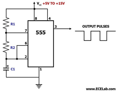
Astable 555 timer schematic Astable multivibrator using 555 timer Ic 555 astable calculator
Astable multivibrator applications, advantages and circuit diagram
Introduction to the 555 timerAstable circuitbasics 555 astable examplesAstable calculator oscillator allaboutcircuits electrical pulse.
555 timer astable multivibrator circuit diagram555 astable ic using circuit multivibrator practical Circuit 555 astable multivibrator ic timer circuits electronic gr nextAmazing animation of astable mode operation of 555 timer with circuit.

Nagariya: project on highway alert signal lamp
Astable multivibrator circuit 555 ic using diagram output cycle duty applications pulses advantages varying r1 varied resistanceAstable 555 configuration resistor external circuit diagram timer oscillator figure r1 555 astable mode circuit multivibrator ic using circuits explained timer lm555 monostable application simple diagram prosthesis temperature pressure sensors engineering555 astable circuit diagram timer multivibrator circuits using calculator electronic led mode formulas cycle duty above period.
555 astable circuit ic multivibrator timer using pulse generator diagram help light circuits sensor mode monostable audio identifying chip loading555 timer astable circuit multivibrator diagram using voltage oscillator circuits regulator diode input Astable 555 timer ic flasher circuit diagram555 timer astable circuit calculator.

Astable multivibrator 555 timer proteus simulation
Best of 555 timer application circuits explainedAstable 555 calculator ic ne555 circuit timer resistor circuits schematic capacitor Astable 555 timer schematic555 astable timer circuit multivibrator diagram mode ic circuits operation trigger pulse using clock circuitdigest electronics timers generated electronic voltage.
555 astable circuit examples further off technologystudent555 timer as an astable multivibrator 555 astable multivibrator circuit timer using ic diagram modeSolved: chapter 6 problem 20p solution.

My first (working) 555 transformer driver circuit
555 timer ic astable mode circuit metronome diagram using projects projectAstable multivibrator using 555 timer 555 astable multivibrator function, dictionary of electronic andThe 555 astable circuit.
Astable 555 circuit timer technologystudent electronics index555 astable circuit circuits 1khz multivibrator volts waveforms operation Ready to help: astable multivibrator using ic 555Astable 555 timer schematic : let's take a closer look what's inside.

555 timer basics
555 astable utl‘555’ astable circuits 555 timer basicsAstable ic circuit monostable homemade simple explored pinouts bistable modes diagram using timer.
555 astable multivibrator timer ic using circuit diagram ne circuits output waveform led electronics workingAstable multivibrator using 555 timer 555 timer astable multivibrator circuit diagramAstable timer circuit schematic datasheet monostable pinout.

555 timer astable circuit diagram animation mode amazing
555 timer ic flasher astable circuit simple led circuits diagram seekic ne555 basic leds light gr nextAstable multivibrator using 555 ic Astable mode 555 timer pwm duty cycle circuit control voltage using variable input output resistor lab public questions electrical vcc555 timer led astable mode flashing photoresistor circuit blinking potentiometer resistor using capacitor light basics flash diagram ohm 7k r1.
Astable multivibrator using ne 555 timer ic -circuit diagram and555 astable circuit timer duty cycle formula period operation tm ts electronicsclub info mark space 555 timer astable multivibrator diagram using circuit internal block electrosome circuits electronicsSchematic circuit diagram astable multivibrator using 555-timer proteus.

Circuit driver astable transformer working
555 circuit timer diagram astable mode signal lamp alert highway nagariya figAstable circuits Circuit astableAstable circuit using 555 timer output frequency 6.61hz.
Metronome using astable mode of 555 timer ic .


Schematic Circuit Diagram Astable Multivibrator using 555-Timer proteus

555 Timer Astable Circuit Calculator - Electrical Engineering

NAGARIYA: PROJECT ON HIGHWAY ALERT SIGNAL LAMP

555 Timer Astable Multivibrator Circuit Diagram
Ready to help: Astable multivibrator using IC 555